|
|
Post Reply 
|
Page 123 4> |
| Author |
 Printable Version Printable Version Google Google Delicious Delicious Digg Digg StumbleUpon StumbleUpon Windows Live Windows Live Yahoo Bookmarks Yahoo Bookmarks reddit reddit Facebook Facebook MySpace MySpace Newsvine Newsvine Furl Furl Topic Search Topic Search  Topic Options Topic Options
|
Pod People 
Senior Member 
Joined: 22 Sep 2011 Location: Chapel Hill,NC Online Status: Offline Posts: 1078 |
 Topic: Installing a Renogy 100 watt Suitcase solar Panel Topic: Installing a Renogy 100 watt Suitcase solar PanelPosted: 16 Jun 2016 at 9:31am |
|
Adding a 100 watt Renogy Suitcase Solar System
Laura and I love to use our pod on long distance, multi-week travels. We like to stay for 3-5 days where we can. A lot of the National and state parks, wildlife refuges and BLM lands do not have power in their campgrounds. We want to stay in beautiful areas and still have the service of our refrigerator, heat, fans and minimal lights at least.
We have learned to conserve power. We use solar powered indoor lights, we have replaced all of the interior bulbs with LED’s, we don’t use the water heater and have purchased very good batteries for our RPod. We need the maximum power (amp hours) from our batteries. We purchased 2 Duracell EGC2 batteries from Sam’s Club. These are 6 volt golf cart batteries that when wired in series combine for 12 volts and 230AH. These batteries without recharging will last us about 2 -3 days with average power usage and minimal furnace usage. We should never let the batteries go below a 50% state of charge to avoid permanent damage. We still needed more power over a longer duration. The obvious answer was that we need a way to recharge our batteries.
I wanted to add a method to recharge the batteries without having to use a generator. So the obvious answer was to use solar power. I wanted to make it as compact as possible, yet also as versatile as possible. I did a lot of research and came across the Renogy 100 watt Suitcase solar system. This system is essentially a “plug and play” self contained solar system. It comes as a folding solar panel that is 20”x27”x3” when folded and weighs 27 pounds. It comes packed in a hard sided nylon padded case. It has a built-in charge controller and a set of lead wires connected to a set of battery clamps. Simply hook the cables to the battery and open the panels and you are charging your battery. Here is the website for the system:
As I researched and thought through this process, I learned about RPod’s new Zamp solar system. I decided that a system that offered a remote panel rather than a permanently mounted panel made more sense. I wanted to be able to park the R Pod in the shade and still have sun available for the solar panel. I decided to use the Suitcase Panel, but use it remotely. This panel setup will allow me to locate the panel some distance from the Pod and allow sun on the panel and shade for the pod. Using a voltage drop calculator, I determined that we could locate the panel up to about 25 feet from the Pod with a 10 gauge wire and have minimal voltage drop (1.74 % or .25volts).
After thinking about the cost and weight of the necessary 25’ of 10 gauge wire, we realized that we already have 25 feet of 10 gauge wire that we carry with us all the time---the 30 amp power cord extension. We seldom need 50’ of power cord, plus if we are off grid we have no need for a power cord at all. So, I have designed a system to work using our extra power cord as the line cord between the suitcase solar panels and the Charge Controller. I called Renogy several times and spoke with their technical advisors. None of them had ever heard of their system being used this way. However, they all agreed that it should work fine.
I made up a parts list and ordered what we needed. Overall, this project cost less than $475-about ½ the cost of a Honda generator. Here is a list of the parts I bought from Renogy 100watt 12 volt Monocrystalline Foladable Solar Suitcase w/o Solar Charge Controller Renogy View Star 20 amp PWM Solar Charge Controller 20amp ANL fuse set w/ extra fuse MC4 assembly tools (2 specialized wrenches) MC4 set (of 5 waterproof connectors) 10amp inline fuse module Renogy does not charge taxes and shipping is free, plus they gave me 10% off for their Memorial Day Sale.
I bought these parts from an online RV parts supplier: 30amp female receptacle and cover 18” male 30amp pigtail
My total cost was under $475. I spent $396.93 with Renogy, $43.56 with an online RV supplier, $21.67 at Lowe’s for 10 gauge wire and assorted electrical parts and $5.85 at a local automotive store for 12 volt electrical connectors and battery cable. I had miscellaneous screws and hardware on hand. I spent a total of about 6 hours wiring and installing all of the parts and pieces. I am happy to report that everything worked the first time. I expect to get 3-5amps at 13-14.2 volts in full sun. That should replenish our batteries daily if we have good weather and be conservative in using electricity.
It was a fun project from start to finish. I learned a lot about solar power and am excited to see it work. The people at Renogy were very helpful in several discussions and technical calls. Their products appear to be well-made, get good reviews and have been available long enough to have a serviceable history. There are lots of You Tube videos concerning this product. This is the Renogy website http://www.renogy.com/
I am happy to report that everything worked the first time. I expect to get 3-5amps at 13-14.2 volts in full sun. That should replenish our batteries daily if we have good weather and be mindful of electricity consumption.
I hope you find this post informative and helpful. Laura gets much credit for editing, re-writing and great photos.
Travel safe
Vann
The rest of this post is a step by step description of how I did this project. Note that there are pictures at the end of the article.
The PROJECT The project was to connect the Solar Suitcase Portable Solar Panels using a standard 25-foot, 30 amp, 10 gauge RV extension cord (that we already owned) to the Pod batteries via a Charge Controller mounted inside the pod.
The Solar Panels and Power Cord: The Renogy 100 watt Suitcase Solar Panels are waterproof, but the Charge Controller that comes mounted on those panels is NOT waterproof. I wanted to mount the Charge Controller inside the pod to keep it out of the weather and be able to monitor the solar panel performance. So, I ordered the solar panels with the same Charge Controller but specified it NOT be attached to the solar panels.
Wiring the solar panels to the Charge Controller requires waterproof electrical connectors. The solar panels come with 18” lead wires permanently connected to the solar panels and outfitted with built-in snap-connectors (MC4) at the other end. MC 4 connectors are a 2-part (male/female) snap system for waterproof electrical connections.
I purchased a kit of 5 MC4 connectors and the 2 proprietary wrenches required for assembly/disassembly. There are several videos on the Renogy site and You Tube that show you that assembling and connecting the MC4 parts is simple, reversible and effective using the proprietary wrenches.
The next step is to attach the male plug to the solar panels. I assembled the MC4 connectors on the end of the male pigtail leads. An in-line, 10-amp PV solar fuse module is required (on the positive wire) between the solar panel and the Charge Controller. I attached this fuse between the solar panel and male pigtail plug end. Note: This system does not need a ground of any type. Thus, we use only the hot and neutral wires and not the ground wire in the pigtail.
So finally, I was able to plug the solar panel’s male plug into the female end of my 25-foot RV extension cord.
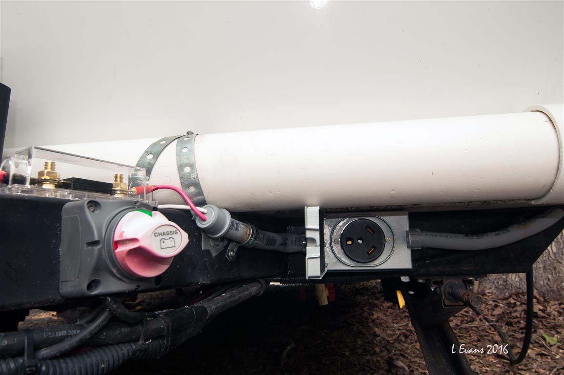
The next step was to mount the female 30 amp receptacle in a waterproof exterior box on the main frame under the front of the R Pod. Once the receptacle is installed, the male end of the extension cord will plug into it.
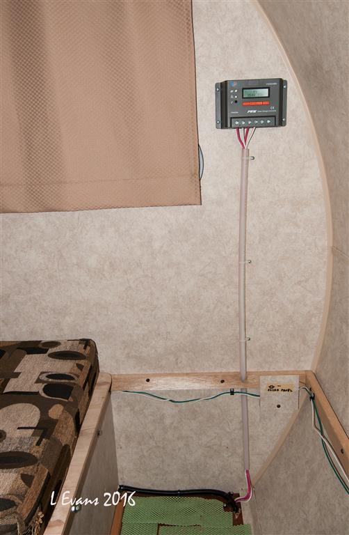
Now, I have to get the wires from the receptacle to the Charge Controller. The Charge Controller is located inside the pod as close to the batteries as possible. The 10 gauge wires from the female receptacle run in ½” PVC conduit to a hole drilled in the floor. I used a heat gun to customize the shape of the conduit. The wires come into the pod inside the front storage area under the dinette seat. I used PEX plumbing pipe as a conduit from the floor up to the Charge Controller. I connected the wires from the 30 amp receptacle to the solar panel input slots (positive and negative) on the Charge Controller. That completes the power input side of the project. Thus the entire sequence of power input consists of the solar panel with an inline 10 amp fuse plugged to the 25’ power cord which is plugged to the 30 amp receptacle which is hard-wired to the Charge Controller.
Power Output from Charge Controller to Pod Batteries I chose the PWM Charge Controller over an MPPT Charge Controller for our solar system. We have only one portable solar panel and it is under 200 Watts. So, we don’t need the considerably more expensive, higher capacity, higher efficiency MPPT Charge Controller.
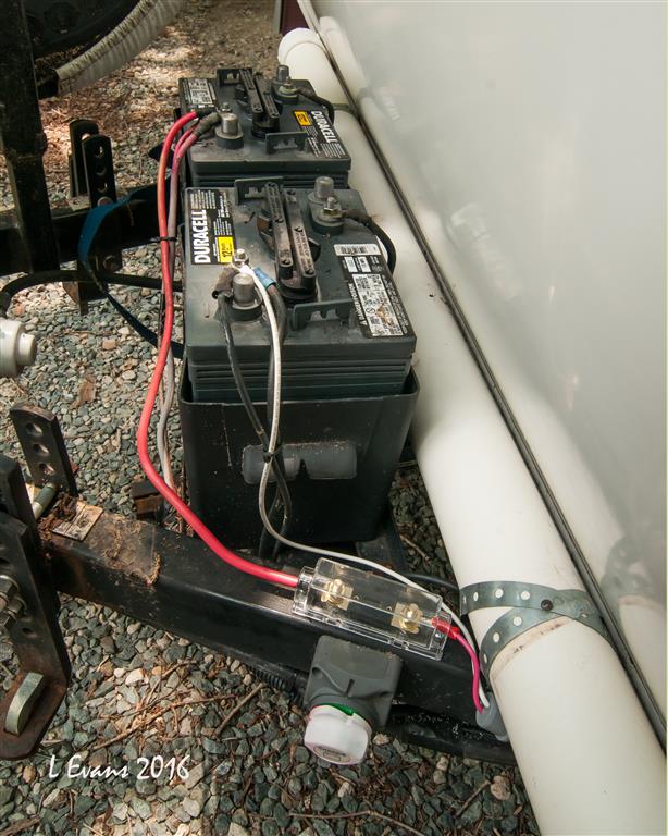
I connected the Charge Controller with 10 gauge output wires to the positive and negative terminals of the battery. I routed the wires from the Charge Controller down the PEX conduit, through the hole in the floor, through a short piece of PVC conduit, through the waterproof receptacle box, through another piece of PVC conduit and out the conduit end cap. The positive wire goes to a 20 amp ANL fuse block that I mounted on top of the Pod’s A Frame. I used a standard automotive battery cable to connect the fuse directly to the positive battery terminal. I used 10 gauge wire to connect the negative line directly from the Charge Controller to the negative battery terminal.
Charge Controller The Charge Controller has a small LCD screen with a number of menus, information and read-outs. It does not require any special programming; it is fully functional out of the box. However, the Charge Controller can be highly customized. The owners’ manual covers what you need to know.
For example, the Charge Controller has these standard screens: How much power is coming from the solar panels to the Charge Controller. How much power goes from the Charge Controller to the Batteries Batteries’ state of charge How much battery power is being consumed
This completes the project.
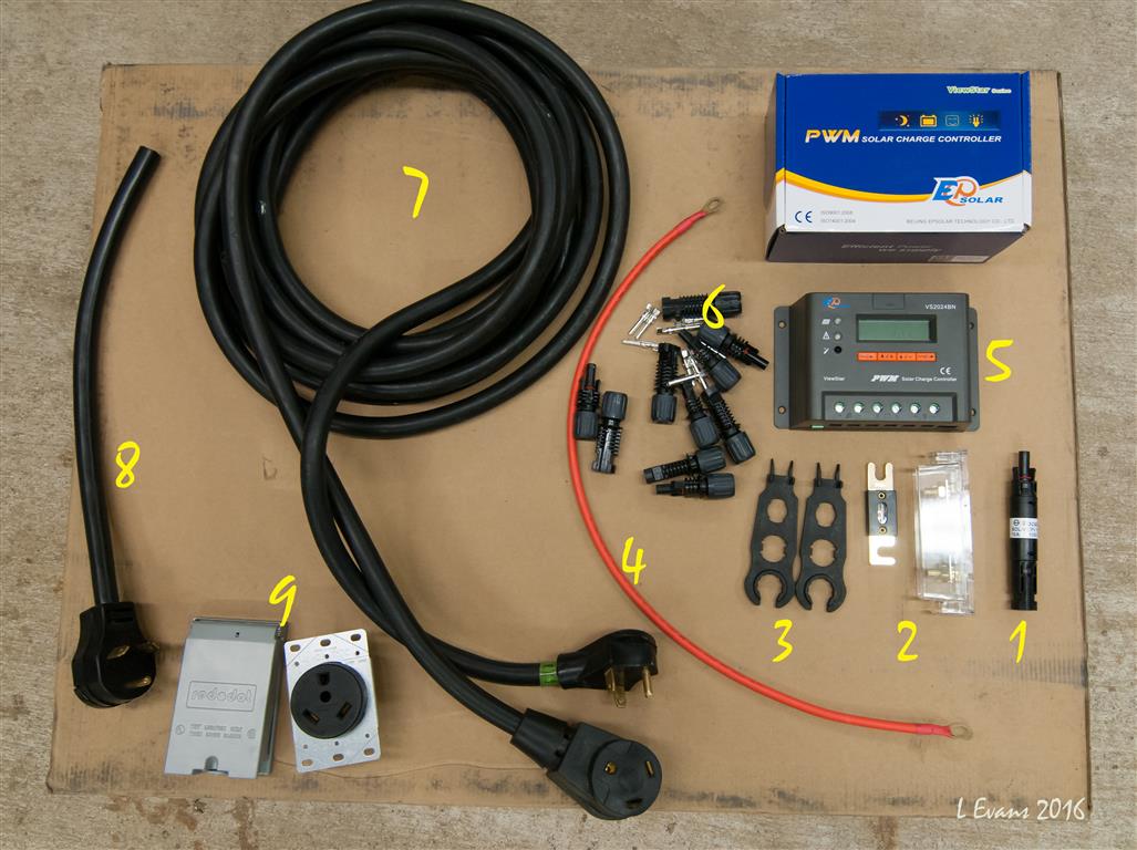
These are the basic materials needed for our installation
1. 10 amp PV solar inline fuse module 2. 20 amp ANL fuse unit 3. MC4 wrenches 4. 24” battery cable 5. Viewstar 20 amp Charge Controller 6. MC4 connectors 7. 25’ 30amp RV power cord 8. 18” male 30amp pigtail 9. 30amp female receptacle and waterproof cover
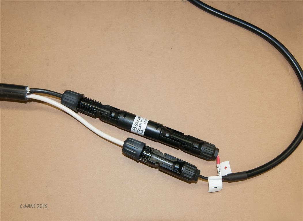
Male pigtail: The positive wire has a female MC4 end connected to the male MC4 of the 10 amp fuse. The female end of the 10 amp fuse is connected to the male MC4 end of the solar panel positive lead wire. The neutral (white) pigtail wire has a male MC4 which plugs into the female MC4 of the solar panel negative lead wire.
Note: This system does not need a ground of any type. Thus, we use only the hot and neutral wires and not the ground wire in the pigtail. Cut the green wire off of the pigtail.
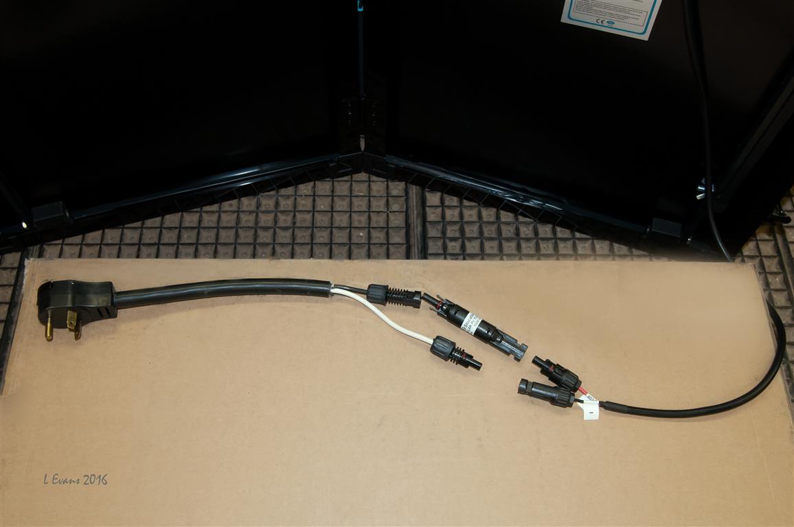
The completed connection between the Solar panel and the male plug
The input system - solar panel, inline fuse, 30amp plug connections between the solar panel and our 30 amp RV extension cord
30 amp receptacle mounted on front frame. ½” PVC conduit with positive/negative output wires from Charge Controller
Charge Controller mounted on wall, PEX plumbing pipe used for conduit
Dual 6v Duracell batteries wired in series (230 amp hours combined) and the 20 amp ANL fuse module
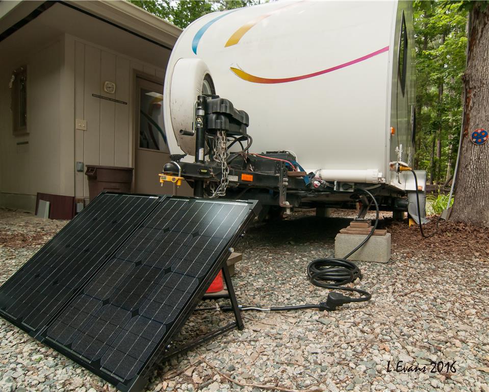
Everything hooked up
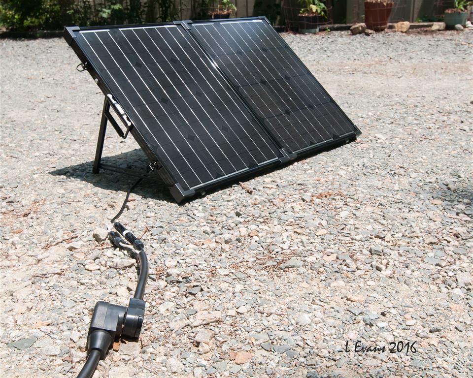
Panels are max distance from pod, Panels are in the sun Pod is in the shade We now have solar power to recharge the Pod's batteries!!
|
|
|
Vann & Laura 2015 RPod 179 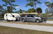
|
|
 |
|
|
Don Halas
Senior Member
Joined: 01 Jul 2015 Location: Connecticut Online Status: Offline Posts: 190 |
Posted: 16 Jun 2016 at 10:11am |
|
The 30 cable adapter you made. Your 3rd photo looks like you have the male end coming off the solar panels. Is that correct? It is my understanding that the panels may produce voltage significantly higher than the 12 volts you'll get on the other side of the charge controller. If that's correct do you have any concern about the male end being live?
|
|
|
|
|
Pod People
Senior Member
Joined: 22 Sep 2011 Location: Chapel Hill,NC Online Status: Offline Posts: 1078 |
Posted: 16 Jun 2016 at 1:13pm |
|
That's a good question.
We did consider this. It was very hard to find a fixed waterproof male connection that could be mounted and wired, so the decision was essentially made for us-we had to use the female end on the trailer. I discussed this with the Renogy technical advisors and they said to make sure the 25' cord was attached to the male plug and also attached at the trailer before opening the solar panels and making the plug ends hot. They also added that in the unlikely event that it did short, the 10 amp inline fuse would blow. It is a simple twist -to-open fuse holder with a standard 10 amp glass fuse that is easily replaceable. The male end will have the 2 prongs exposed and could be shorted if the panels are open and both of the plug end touches something . I will wait and see if it becomes a problem. I could get a unwired female receptacle to cover the male end if it becomes an issue. Thanks for the question. I see you are also hooking up a solar system. I hope some of my post was helpful in your application. Vann. |
|
|
Vann & Laura 2015 RPod 179
|
|
|
|
|
Don Halas
Senior Member
Joined: 01 Jul 2015 Location: Connecticut Online Status: Offline Posts: 190 |
Posted: 16 Jun 2016 at 1:52pm |
|
For whatever it's worth my installation which I am going to complete this weekend will have connectors just before the charge controller so I can disconnect them and not worry about having hot leads coming from the solar panel.
I know it's low voltage, but never a good idea to have it exposed. |
|
|
|
|
bluecatjudy
Newbie 

Joined: 27 Jan 2016 Location: Florida Online Status: Offline Posts: 15 |
Posted: 16 Jun 2016 at 5:08pm |
|
Great Mod and information. I also installed a 100watt Renogy solar panel on my Rpod this week. I have a 2016 179 with the solar plug already installed. I crawled under the stove and rerouted the wires going to the plug. I mounted a 30A Renogy Adventurer controller in the cabinet as you walk in the door. I know it was over kill for a 100 watt solar panel but it mounted flush with the cabinet and no wires exposed. I used an inline fuse at the controller and another in the battery box. I bought 20 feet of wire from the panel to the solar plug. i was getting 5.5 amps after plugging it in. I like the led display and convenience of plug and charge. My wife made a sunbrella cover for it when we are traveling and we store it in the bathroom.
We should have a contest who gets the best charge. Of course there is other variables not just your cord. I get more sun in Florida but I have noticed on my boat's solar panel it charges better in colder weather. I would post a picture but for the life of me I can not figures it out. Can anyone help me? I am on a Mac book pro.
|
|
|
sailorman
|
|
|
|
|
Westgl
Newbie

Joined: 07 Jun 2016 Location: Oregon Online Status: Offline Posts: 35 |
Posted: 19 Jun 2016 at 5:23pm |
|
I have a 2017 179 and also have the renogy 100w solar suit case panel. I would love to see a picture of were you mounted the controller at. did you remove the controller that comes mounted on the renogy panels and relocate it inside the pod? If so I like that idea. keeps the controller out of the wet weather as it is not weather proof, but solar panels are weather proof, just incase a storm sneaks up on you, the controller would be safe, I like it!!! I would love some pictures.
|
|
|
2010 RAV4 V6
2017 RPOD 179 Hood River Edition Dual 6 volt Batts Dual propane Tanks Batt Disconnect Bed leg extension Dinette modification Renogy 100w solar Motorcycles several currently |
|
|
|
|
bluecatjudy
Newbie
Joined: 27 Jan 2016 Location: Florida Online Status: Offline Posts: 15 |
Posted: 19 Jun 2016 at 11:25pm |
|
I have been trying to upload pic but i am new to the forum and have not "got" it yet. I bought a 100 watt panel with no controller. It was about $120 on Amazon. I bought the controller separately for $75 on eBay. It is flush mounted so you see no wires and mounted it in the counter as you walk into the tt. It's a great controller as it tells me volts at the battery, volts at the panel and amps. It has option for temperature but the wires are only about 6 feet. If you crawl under the cabinet there is a panel easily removed from the back which will expose the wires from the solar port. Cut the wires at the splice and run those to the battery side of controller. Spice 4 feet 10 gauge wire from Home Depot to the port and run it to the solar panel side of controller. Add 2 fuses and wire from the solar panel to the port;and, your done.
|
|
|
sailorman
|
|
|
|
|
Pod People
Senior Member
Joined: 22 Sep 2011 Location: Chapel Hill,NC Online Status: Offline Posts: 1078 |
Posted: 09 Jul 2016 at 9:39am |
|
I have added a female end for the male plug that is connected to the solar panels. This will prevent any accidental exposure to a shock if someone touches both contacts of the male plug. It essentially a yellow "hockey puck" 15 amp to 30 amp adapter .
Vann
|
|
|
Vann & Laura 2015 RPod 179
|
|
|
|
|
JandL
Senior Member

Joined: 29 Mar 2014 Location: California Online Status: Offline Posts: 364 |
Posted: 09 Jul 2016 at 8:29pm |
|
The solar panel outputs a DC voltage and the MC4 connector coming off the panel are very good sealed connectors for DC voltage. Adding the extra AC connector is not how I would have done it. It’s not a good idea to mix AC and DC connectors. Someday someone might not be paying attention and plug the wrong power source into the wrong connector. If you need to add a DC panel mount connector[ https://powerwerx.com ] carry’s Anderson Powerpole connectors. Also Marinco makes a panel mount ConnectPro Plug & Receptacle for Trolling Motor, 3 wire which will take up to a 8 gauge wire and a 2 Wire ConnectPro Receptacle and Plug Combo, 2 wire that take up to a 10 gauge wire. The ANL fuse is going to give you problems as it will start to corrode due to exposure to the weather. You could use a Bussmann HHR ATC Holder Waterproof fuse holder with locking cap, up to 30 amps, 12 gauge leads also White Products has the same thing in 10 gauge [ http://www.whiteproducts.com/sfh-ato.shtml ] this fuse holder would easily fit under your battery cover. Two other good sites for Automotive wiring are Del City [ http://www.delcity.net ] and Waytek [ https://www.waytekwire.com ]
|
|
|
JandL
2013 Honda Ridgeline 2012 177 2 Paynes in a Pod |
|
|
|
|
WillThrill
Senior Member

Joined: 04 Jul 2014 Online Status: Offline Posts: 298 |
Posted: 09 Jul 2016 at 9:03pm |
I'm no electrician, but why would it be bad to mix AC and DC connectors? Electrical current doesn't care what kind of wiring it's flowing through. I know that AC and DC breakers are different, along with electrical board components, but connectors for solar panels? I agree that the ANL fuse holder needs to be sealed somehow to prevent water intrusion.
|
|
|
"Not all those who wander are lost." Tolkien
2014 Hood River 177 2005 GMC Envoy XL |
|
|
|
|
Post Reply
|
Page 123 4> |
| Forum Jump | Forum Permissions You cannot post new topics in this forum You cannot reply to topics in this forum You cannot delete your posts in this forum You cannot edit your posts in this forum You cannot create polls in this forum You cannot vote in polls in this forum |


 Installing a Renogy 100 watt Suitcase solar Panel