
|
|
Post Reply 
|
Page 123 6> |
| Author |
 Printable Version Printable Version Google Google Delicious Delicious Digg Digg StumbleUpon StumbleUpon Windows Live Windows Live Yahoo Bookmarks Yahoo Bookmarks reddit reddit Facebook Facebook MySpace MySpace Newsvine Newsvine Furl Furl Topic Search Topic Search  Topic Options Topic Options
|
offgrid 
Senior Member 
Joined: 23 Jul 2018 Online Status: Offline Posts: 5290 |
 Topic: Lithium Battery install ? Topic: Lithium Battery install ?Posted: 31 Oct 2019 at 8:20am |
|
I couldn't follow where all those FR breakers were and some seem undersized to me. Here's what I'd do. I'd dispense with those hidden FR breakers and wire up as shown in the schematic below. I like simple, safe, and robust, with as much as possible in one place.
The objective of having overcurrent protection is to be sure you are protecting all your +12V conductors in case they get a fault to ground. The fault currents are going to come from the batteries if that happens. So, I am showing a 30A breaker at the TV battery (you probably have that already) and a 50A breaker at the trailer (Li) battery. That could be a fuse instead. I would put it as close to the battery as possible, preferably a bolt on device right on the battery terminal itself. A 50A fuse protects down to 6 gauge so everything downstream of the 50A fuse or breaker (until you get to the next converter, charger, or panel) should be 6 AWG or larger. 30A protects 10 gauge so same thing there. The reason for 50A and not 30 from the trailer battery is that 30A might be a little shy when operating the slide if you have anything else on at the same time. You could test that and go with 30A and 10AWG if you wanted to. This is a single line diagram so I'm not showing any of the negative conductors. They should be a min 10AWG on the TV and 6 on the trailer in order to be able to handle the maximum return currents that can pass through the respective circuit breakers or fuses. Those conductors could go to the frame, that's fine. I would also add a battery current shunt for monitoring. That would go in the battery negative conductor (not shown). I'd also have a high voltage and a high temp safety disconnect for the Li battery (also not shown). Hope that helps. 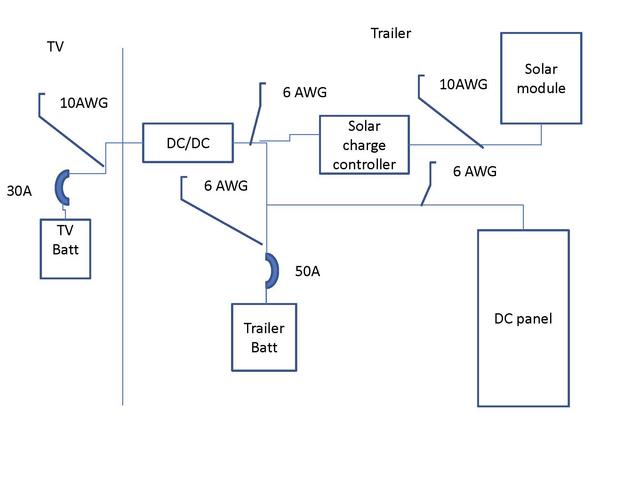 |
|
|
1994 Chinook Concourse
1995 RV6A Experimental Aircraft 2015 Rpod 179 - sold |
|
 |
|
|
Olddawgsrule
Senior Member
Joined: 20 Sep 2017 Location: New Hampshire Online Status: Offline Posts: 1014 |
Posted: 30 Oct 2019 at 11:05am |
|
Test out/traced the wires and here's what I see now.
Yes, there is a fuse between the 7pin 12v (#4 pin) and the rPod battery. And yes there is a fuse on the Solar-on-the-side line. Both enter the 30a auto-breaker (underneath, Portside, fore) just before the battery. Well, at least on my 2017 182g they are. There is also a 30a auto-breaker prior to the panel where the #4 12v line and the battery cable meet. Here's my chart.  |
|
|
|
|
Olddawgsrule
Senior Member
Joined: 20 Sep 2017 Location: New Hampshire Online Status: Offline Posts: 1014 |
Posted: 29 Oct 2019 at 2:18pm |
|
Well, got started between rain drops.. So far I haven't located/comfirmed the line back from the TV to the panel area. What I did find was a bit disappointing..
Now, I have read some pretty good arguments that there can be logic to chaos.. One of those believers wired my trailer! What a rat's nest of wires! Worst are these two wires.. If anyone can identify, please do.. This one comes out of the DC side of the panel box. End is flatten like it was connected to something..  This one looks like it comes out of that red whatever (some sort of fused splice I think) but it actually passes under that and runs back into the abyss of wires.. Again, flatten end like it was connected somewhere.  Next is what I believe to be the Converter charger return. And yet another of those auto breakers hidden away never to be found by the average consumer..  In that last picture you see two wires on a side and the single that is running the the panel box. I need to ring both these out, but I think this is the 7 pin and the battery cable meeting up. If this is so, it explains another fuse here before the panel. And if indeed so, that makes the DC side 30amp max, at least from TV or battery. Lastly, I was hoping to find the Converter/charger was a separate unit from the panel. Not going to be that easy.. It's integrated. I'll read some more on the repair to the WFCO that another member (here?) posted and possibly reach out to see if a switch can be installed. A bit more time required on this part. Most important right now is if anyone can identify those loose wires? |
|
|
|
|
Olddawgsrule
Senior Member
Joined: 20 Sep 2017 Location: New Hampshire Online Status: Offline Posts: 1014 |
Posted: 29 Oct 2019 at 7:31am |
Is that not what the Auto-breaker is? The real dusty module you see.  I'll be getting to the panel hopefully later this week, with this off & on rain it's been tough getting anything accomplished outside.. I want to see just where and how the hot wire from the pin ties in and how the WFCO is tied in. That will help with decisions of what & how I proceed. I have say OG, shutting off the breaker sounds far too easy! Nothing is ever that simple.. LOL
|
|
|
|
|
offgrid
Senior Member
Joined: 23 Jul 2018 Online Status: Offline Posts: 5290 |
Posted: 29 Oct 2019 at 6:17am |
|
Yes, true, if you connect the dc dc converter where you're suggesting you're not interfering with any existing overcurrent protection. The reason to add a battery fuse is because there should be one there, FR is remiss in not having one there already in my opinion. That is where the current is going to come from if you have a conductor or charge controller fault, and you're not protected now. Any halfway decent power circuit designer will tell you that is bad practice.
If you disconnect the dc side of the wfco it won't do any charging, but if you leave the ac side on it will remain energized when you're plugged in. Just turning the breaker off and taping it as a reminder will fix that. You could also go in there and disconnect the ac from the wfco but then you'd have to remove those conductors or otherwise protect them from shorting out. Shutting the breaker off accomplishes the same thing. I don't think you've missed anything other than I suggest you get a good understanding of what the BMS in your Li battery does and doesn't do. It needs as a minimum to do cell balancing. Some also provide a backup max voltage cutoff, and some also have a thermal cutoff. If yours doesn't have those features, depending on your risk tolerance you might want to add them externally, Victron for one has a product that does that. Consider that you will be sleeping on top of this battery which could catch fire if it ever gets seriously overcharged...unlikely but not impossible...
|
|
|
1994 Chinook Concourse
1995 RV6A Experimental Aircraft 2015 Rpod 179 - sold |
|
|
|
|
Olddawgsrule
Senior Member
Joined: 20 Sep 2017 Location: New Hampshire Online Status: Offline Posts: 1014 |
Posted: 28 Oct 2019 at 4:16pm |
Thank you for responding, I was awaiting you! As I sit right now, I've been able to recharge the PbA's (dual 6v's) and run the Frig (on battery) while driving. That tells me I have enough amps coming through to maintain. I no longer battery run the frig while driving. I find propane to be so efficient, inexpensive and easy. Now the system just has to re-charge the batt's. System is good and TV power is good (not all can state that). Question becomes:What have I missed here? I'm not asking to draw anything greater than what I have already and use. Question is: Am I tapping in at the right spot? I 'think' I am...
|
|
|
|
|
offgrid
Senior Member
Joined: 23 Jul 2018 Online Status: Offline Posts: 5290 |
Posted: 28 Oct 2019 at 2:27pm |
|
Looks like you're on a good track.
Just a couple of suggestions. If you place your solar charge controller in the same area then you'll have all your power electronics in one place. Overcurrent protection: I would add a fuse at the battery + terminal. That is where the high current is going to come from in the event of an electrical fault in the dc circuit. There should already be a 30A breaker on the conductor to the 7 pin connector at the TV battery so that line is protected. If you're running 10 gauge then use a 30A fuse, but its possible that might blow if you operate the slide while some other loads are on. 6 AWG would be better, with a 50A fuse. You can physically disconnect the 12V side of the WFCO, nothing wrong with that, but I'd suggest also turning and taping off its ac circuit breaker so it doesn't ever get energized. If you add a battery monitor that actually clocks amphours in and out you will have a way to monitor true battery state of charge on that expensive Li battery to replace the crappy lights that won't work for Li anyway. if you do, get one that uses an actual inline current shunt not a hall effect donut, those drift a lot.
|
|
|
1994 Chinook Concourse
1995 RV6A Experimental Aircraft 2015 Rpod 179 - sold |
|
|
|
|
Olddawgsrule
Senior Member
Joined: 20 Sep 2017 Location: New Hampshire Online Status: Offline Posts: 1014 |
Posted: 28 Oct 2019 at 11:48am |
|
Flow Chart 
|
|
|
|
|
Olddawgsrule
Senior Member
Joined: 20 Sep 2017 Location: New Hampshire Online Status: Offline Posts: 1014 |
Posted: 28 Oct 2019 at 11:35am |
|
Okay, that was the easy part! The battery is not direct wired off the 7 pin.
This is the mess underneath with the splices and auto fuses.  Top and right top is the 7 pin line from the TV to the splices above. This is the 12vdc line from the 7pin  Here the same line heads back towards the panel. Those two Red lines above are returns.  The two return reds now connect to the auto fuse.  Out the other side of the auto fuse and onward to the battery.  . .  Now for the decision of where to tap in.. To keep in mind here.. I'm going to dis-connect the Converter/Charger, it will not longer be part of the system. With that said, I still believe I can tap into the 7 pin splice. If so, this could be very easy as I would only need to re-route the battery cables and connect up the lithium battery. Thoughts??? |
|
|
|
|
Olddawgsrule
Senior Member
Joined: 20 Sep 2017 Location: New Hampshire Online Status: Offline Posts: 1014 |
Posted: 28 Oct 2019 at 10:38am |
|
Found it! 7 pin leads/line splices right up front underneath the camper, 182g port side. Just follow the connection pigtail back to the camper and you'll see the splices and the auto-breaker.
This is where I tapped in the for the inverter I had in there before. I already have the hole/grommet to run the wires. I was hoping for this! This will place the Dc/Dc charger up by my water heater and right where I hoped to place the lithium battery. Rain has let up, so I'm taking advantage while I can. I'm updating as I print out the pin positions to ohm out the 12v line.
|
|
|
|
|
Post Reply
|
Page 123 6> |
| Forum Jump | Forum Permissions You cannot post new topics in this forum You cannot reply to topics in this forum You cannot delete your posts in this forum You cannot edit your posts in this forum You cannot create polls in this forum You cannot vote in polls in this forum |


 Lithium Battery install ?