|
|
Post Reply 
|
Page 12> |
| Author |
 Printable Version Printable Version Google Google Delicious Delicious Digg Digg StumbleUpon StumbleUpon Windows Live Windows Live Yahoo Bookmarks Yahoo Bookmarks reddit reddit Facebook Facebook MySpace MySpace Newsvine Newsvine Furl Furl Topic Search Topic Search  Topic Options Topic Options
|
CharlieM 
Senior Member 
Joined: 23 Nov 2012 Location: N. Colorado Online Status: Offline Posts: 1797 |
 Topic: Mods for Camplite 21RBS Topic: Mods for Camplite 21RBSPosted: 04 Mar 2014 at 2:02pm |
|
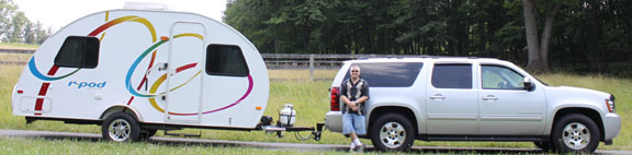
A few mods to my 2014 Camplite 21RBS. Although these are for the Camplite they came about from my RPOD experience and the help from this forum. I think this will just about complete the outfitting project. Now off to the campground!
2. 3. 7. 9.
|
|
|
Charlie
Northern Colorado OLD: 2013 RP-172, 2010 Honda Pilot 3.5L 4WD PRESENT: 2014 Camplite 21RBS, 2013 Supercharged Tacoma 4L V6 4WD |
|
 |
|
|
techntrek
Admin Group - pHp 
Joined: 29 Jul 2009 Location: MD Online Status: Offline Posts: 9062 |
Posted: 04 Mar 2014 at 2:23pm |
|
I looked up the SeeLevel but can't find how it detects the level. Info?
|
|
|
|
|
CharlieM
Senior Member
Joined: 23 Nov 2012 Location: N. Colorado Online Status: Offline Posts: 1797 |
Posted: 04 Mar 2014 at 2:51pm |
|
Doug,
You'll love this. When I started camping with my Pod and was having the normal difficulty with the black tank monitor I concluded there was no fix with that that technology. Most advice came down to "live with it". But, being the engineer, I thought I thought: I could design a sensor to measure the capacitance between two plates on the side of the tank, using no internal probes. The rising liquid level could be sensed as a change in capacitance or AC impedance as the level covered multiple sensor points. Well guess what. That's how the SeeLevel works. All with no development work by me......and no royalties  . I just installed the system so a field test is scheduled this weekend. The only complaint I have read on the external sensors is that they may fall off if not properly applied. But with proper surface sanding and cleaning they should work. The Seelevel sensors are adhered using 3M 300LSE adhesive. Google it! Some wicked stuff, advertised to stick to Polypro and Polyethylene. Nothing sticks to PE so time will tell. Great customer service from Garrett too. . I just installed the system so a field test is scheduled this weekend. The only complaint I have read on the external sensors is that they may fall off if not properly applied. But with proper surface sanding and cleaning they should work. The Seelevel sensors are adhered using 3M 300LSE adhesive. Google it! Some wicked stuff, advertised to stick to Polypro and Polyethylene. Nothing sticks to PE so time will tell. Great customer service from Garrett too. |
|
|
Charlie
Northern Colorado OLD: 2013 RP-172, 2010 Honda Pilot 3.5L 4WD PRESENT: 2014 Camplite 21RBS, 2013 Supercharged Tacoma 4L V6 4WD |
|
|
|
|
techntrek
Admin Group - pHp
Joined: 29 Jul 2009 Location: MD Online Status: Offline Posts: 9062 |
Posted: 04 Mar 2014 at 4:58pm |
|
Interesting, capacitance. Makes sense. And nothing inside the tank at all is perfect.
I've had a few of those ideas over the years!
|
|
|
|
|
CharlieM
Senior Member
Joined: 23 Nov 2012 Location: N. Colorado Online Status: Offline Posts: 1797 |
Posted: 04 Mar 2014 at 5:43pm |
|
Technically they don't really measure capacitance, but the result is the same. I think they detect an AC current between a common "transmit" pad and individual "receive" pads. The paths are through the plastic tank wall, through the liquid, and back through the wall. In effect you have 2 capacitors connected in series by a liquid path. There seems to be some measurement of signal level because the display increments in smaller increments than would be expected for the number of pads on the sensor board. For example a sensor with 4 pads increments at 6-7% as the tank fills. No idea how accurate it is but it's fun to watch.
|
|
|
Charlie
Northern Colorado OLD: 2013 RP-172, 2010 Honda Pilot 3.5L 4WD PRESENT: 2014 Camplite 21RBS, 2013 Supercharged Tacoma 4L V6 4WD |
|
|
|
|
bhamster
Senior Member
Joined: 19 May 2011 Location: Washington Online Status: Offline Posts: 165 |
Posted: 04 Mar 2014 at 5:58pm |
|
Ditto here. I also had a crazy idea to check the tank level using resonance (think blowing into a beer bottle). Then I found the SeeLevel and decided to use their proven approach over my theories. The price is a steal when you consider I would spent 20+ hours coming up with my own.
But being the tinkerer that I am, I decided not to use the display that came with it. I've reverse engineered their one-wire protocol to add it to my own custom unified RV monitor. The current plan is to use a 2.2" color LCD to display the following information: AC Volts AC Frequency AC Current EMS Status (in readable text) DC Volts DC Current Fresh Tank Level Grey Tank Level Black Tank Level Inside Temperature/Humidity Outside Temperature/Humidity Water pressure Items in bold obviously come from the SeeLevel sensors. All the "AC" and "EMS" info comes from the surge protector. But I had to reverse engineer the surge protector protocol too. Their display was hideous: 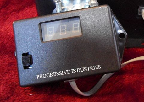 No thanks, they can send that display back where it came from... the 90's Here's the best part: the surge protector that I bought was $50 less because it didn't have a display, but they use the same circuit board and microcontroller inside. So the remote display signal was still being sent, I just have to solder on some headers. Once my ultimate RV monitor is complete I'll post pictures and details. Charlie- did you have to chop the seelevel sensors to fit the tanks?
|
|
|
|
|
kymooses
Senior Member

Joined: 01 Aug 2010 Location: Louisville, Ky Online Status: Offline Posts: 1807 |
Posted: 04 Mar 2014 at 6:02pm |
|
Will be looking forward to this ultimate RV monitor panel mod!
|
|
|
|
|
CharlieM
Senior Member
Joined: 23 Nov 2012 Location: N. Colorado Online Status: Offline Posts: 1797 |
Posted: 04 Mar 2014 at 6:26pm |
|
Travis,
Sounds great and very interesting. A real exercise in microprocessor programming. And what is EMS status? Yes I did cut the sensors. The fresh and gray sensors are standard 709ES boards cut to 4.5 and 6 inches. The black sensor is a 709JS which can be cut to 4 inches and have 4 sensor pads. When you get ready to work on that, and before you order, get back with me. There are some tricks of the trade. |
|
|
Charlie
Northern Colorado OLD: 2013 RP-172, 2010 Honda Pilot 3.5L 4WD PRESENT: 2014 Camplite 21RBS, 2013 Supercharged Tacoma 4L V6 4WD |
|
|
|
|
bhamster
Senior Member
Joined: 19 May 2011 Location: Washington Online Status: Offline Posts: 165 |
Posted: 04 Mar 2014 at 6:39pm |
|
The EMS stands for "Electrical Management System" and is made by Progressive Industries. Here's the unit I purchased:
http://www.progressiveindustries.net/ems_lchw30.htm Similar to the surgeguard, but seemed higher quality and more hackable. The "EMS Status" is normally a code that shows up on that wonderful display. It will say something like "E01" and you're supposed to either memorize or keep a card around that tells you what condition that is (1 is reverse polarity). Well my beautiful LCD display will just say "Error: Reverse polarity". Much easier to see what's going on. In the rpod I had a surgeguard and when it wouldn't click in I'd have to get out the multimeter to see what was going on (usually the post outlet was dead). Now you've got me worried... what are the tricks of the trade? I already have the SeeLevel in hand. Yesterday I completed the reverse engineering by taping it to the side of my water jug and slowly filling. The onewire protocol actually sends readings for all 8 pads (1 byte each) and the control panel converts them to the number you see on the screen. So even though the display will only give you increments of 3-4%, the readings themselves are actually very detailed (though they might fluctuate too much to be reliable at that detail). There's one pesky checksum byte that I'm trying to figure out, but that's just for S&G's, it's not strictly required to take a reading.
|
|
|
|
|
CharlieM
Senior Member
Joined: 23 Nov 2012 Location: N. Colorado Online Status: Offline Posts: 1797 |
Posted: 04 Mar 2014 at 7:11pm |
|
The "tricks" I found are:
|
|
|
Charlie
Northern Colorado OLD: 2013 RP-172, 2010 Honda Pilot 3.5L 4WD PRESENT: 2014 Camplite 21RBS, 2013 Supercharged Tacoma 4L V6 4WD |
|
|
|
|
Post Reply
|
Page 12> |
| Forum Jump | Forum Permissions You cannot post new topics in this forum You cannot reply to topics in this forum You cannot delete your posts in this forum You cannot edit your posts in this forum You cannot create polls in this forum You cannot vote in polls in this forum |


 Mods for Camplite 21RBS