|
|
Post Reply 
|
Page <12 |
| Author |
 Printable Version Printable Version Google Google Delicious Delicious Digg Digg StumbleUpon StumbleUpon Windows Live Windows Live Yahoo Bookmarks Yahoo Bookmarks reddit reddit Facebook Facebook MySpace MySpace Newsvine Newsvine Furl Furl Topic Search Topic Search  Topic Options Topic Options
|
jato 
Senior Member 

Joined: 23 Feb 2012 Location: Kewadin, MI Online Status: Offline Posts: 3227 |
 Topic: 120-Watt Solar System for Rpod Topic: 120-Watt Solar System for RpodPosted: 31 Oct 2016 at 4:56pm |
|
Really interesting Russ. How much of an investment has this set you back thus far? Will be interesting to know how it works out in the real world. Please keep us posted!
|
|
|
God's pod
'11 model 177 '17 Ford F-150 4WD 3.5 Ecoboost Jim and Diane by beautiful Torch Lake "...and you will know the Truth and the Truth will set you free." |
|
 |
|
|
Rustler
Senior Member

Joined: 07 May 2016 Location: S. Oregon Coast Online Status: Offline Posts: 100 |
Posted: 31 Oct 2016 at 2:29am |
|
I have been wanting to report on my implementation of a solar charging system on our 2016 Rpod 171. I had previously reported on progress made in an earlier forum posting. Due to a glitch in the website many of my earlier photos had been deleted. So here is an updated post of my completed solar system. I was guided by a couple of personal preferences in deciding how to proceed:
While our Rpod 171 has the “Solar Ready” SAE connector, I opted not to use it for the following reasons:
That SAE solar-ready connector can be used for an external (unfused) DC outlet.
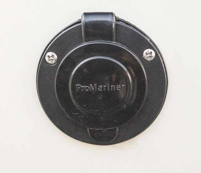
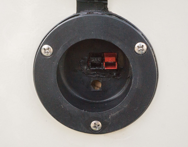
So I decided to locate a powerpole entry flange closer to the battery, that is on the left side near the front. Since I could not locate a suitable pre-made, water-resistant powerpole entrance connector, I fashioned one from a ProMariner AC Plug Holder.
This is designed to hold the male end of a 3-prong AC extension cord, allowing a shore power cord to be plugged in. But I adapted this to hold a pair of powerpole connectors instead.
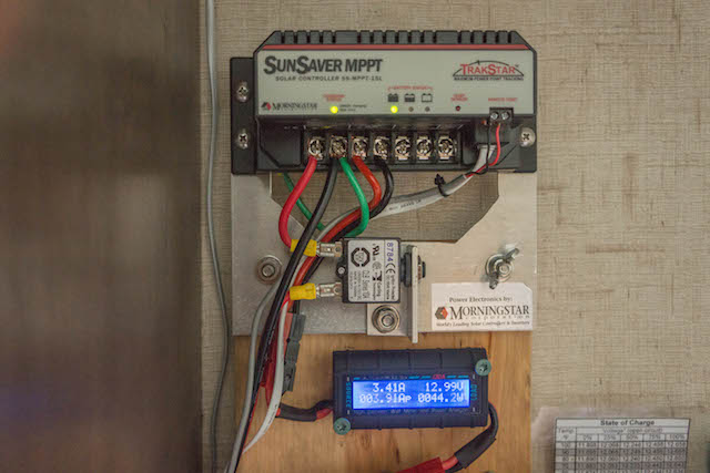
Part of my rationale for using a high voltage solar panel is that not only is the voltage higher, the current is correspondingly lower for the same power level. This lower current means any voltage drop due to wiring and connectors is less. Also that voltage drop is a smaller percentage of the higher voltage. So going from a 12 volt to a 24 volt panel lowers the percent voltage drop by a factor of 4 - half the current induced voltage drop and twice the comparison voltage. The up side of all this is you can go 4 times further with a given gauge wire having the same percent voltage drop. Thus when the trailer is parked in the shade, the solar panel can be located at some distance in full sun. I’ve been able to use 75 feet of 10 gauge tray cable in this way to good advantage. By the way a 24-volt solar panel is no more dangerous that a 12-volt panel. Despite the higher voltage, current is limited to the short circuit output of the panel. This short circuit current is not much higher than the current at maximum power point, easily handled by properly sized wiring. In the case of my 120-watt solar panel maximum power is at 34.4 volts with 3.49 amps, while short circuit current is just 3.86 amps Using a 24-volt panel to charge a 12 volt battery is facilitated by a maximum power point tracking (MPPT) charge controller. This controller operates the solar panel at a voltage giving the greatest power. The voltage is then converted (at over 95% efficiency) to that necessary for charging the 12 volt battery. I installed my Morningstar Sunsaver MPPT-15L above the left side window above the dinette seating, close to the powerpole inlet receptacle. For all interior wiring I used 10 gauge red/black zip cord.
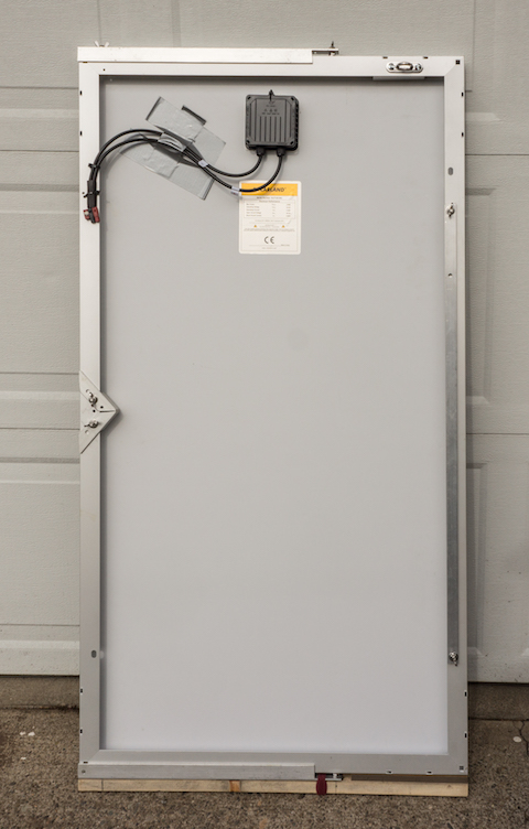
The solar panel I chose is the Solarland SLP120-24U from Sunshineworks.com. My wife made a nice canvas cover to protect the panel while in storage or transport.
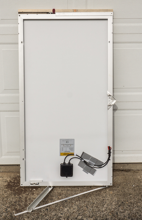
The next photo shows the back of the panel after removal from its canvas cover.
On top and bottom are aluminum support braces that swing out to tilt the panel up to receive sunlight. Stored along the right edge is a stack of the two bottom braces. On the left is the front center support in its stowed position. On the top right is a security loop attached to the panel with security screws, which cannot be unscrewed. This provides a point to attach a security cable to discourage theft. I have a 25-foot stainless steel cable for security if needed. This can be locked to the panel at the security loop. Finally on the bottom is a wooden piece that protects the bottom of the canvas cover from being damaged by the wing nuts holding the brace. All braces are aluminum, and all attachment bolts, nuts & washers are stainless steel.
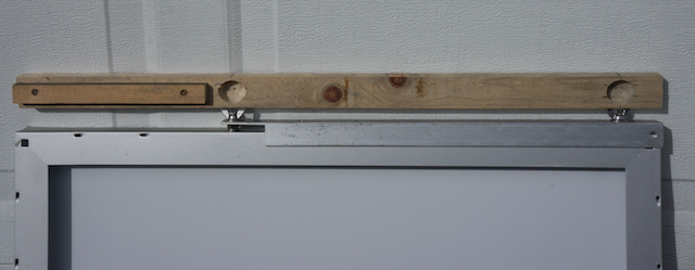
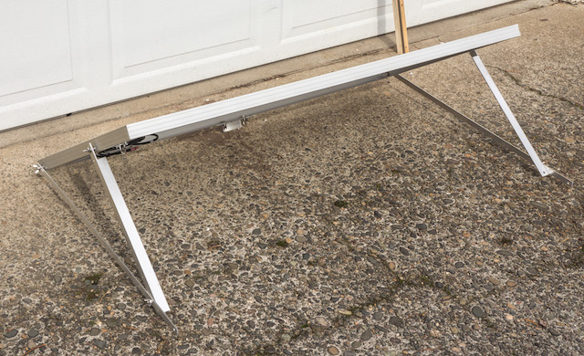
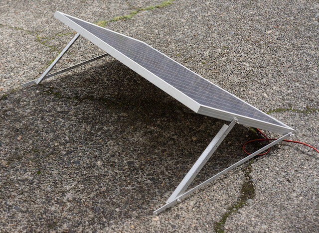
Above you can see one of the assembled braces. The front center support can be seen on the right flipped around to its extended position. This allows for three point ground contact for optimum stability. On top is the wooden protective piece covering the wing nuts. The next photo shows this wood piece removed.
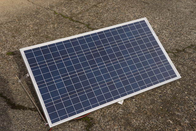
Above we see both brace assemblies and front center supporter deployed. Next photo shows the panel from the sunward side.
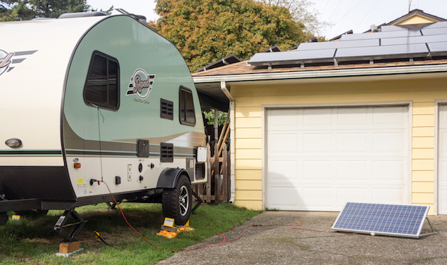
Next we see the panel deployed in the sun near the Rpod 171.
The horizontal bottom braces have holes drilled in different locations for changing their effective length to vary the tilt with the seasons.
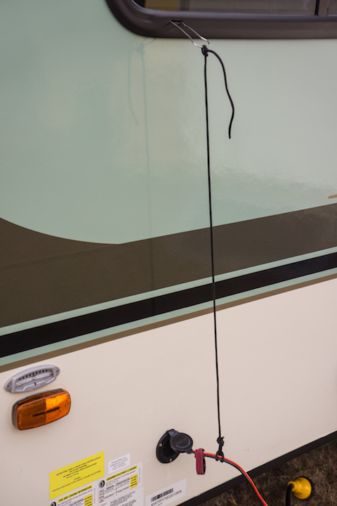
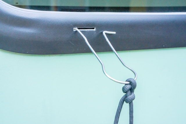
Above we can see the powerpole inlet jack with the 10 gauge zip line being supported by a length of black nylon parachute cord. This was necessary since the powerpole connectors are not designed to withstand a sideways or twisting force that could be exerted by the zip line. I needed an attachment point above to anchor the parachute cord. To provide this without drilling a hole in the Rpod wall I utilized the drain slot below the window as shown below.
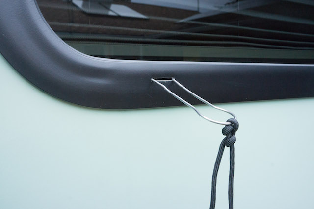
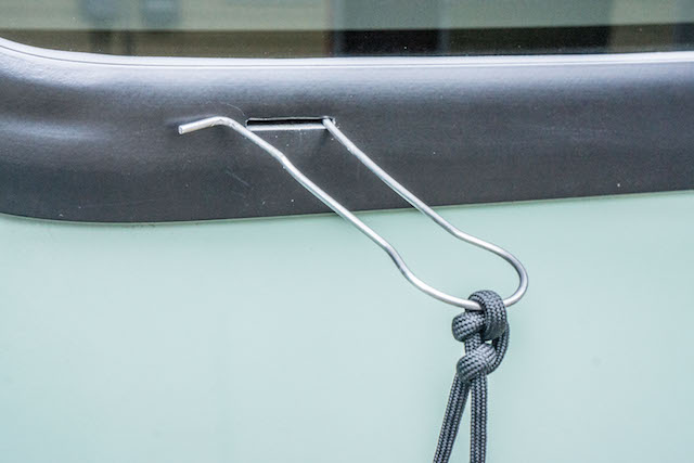
The wire used in the loop is a very stiff steel, which is difficult to bend. But it flexes enough to allow inserting the two ends into the drain slot, as shown in the photos below.
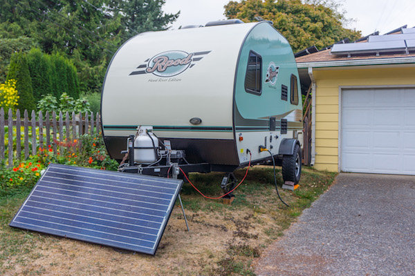
Below is the 120-watt solar panel deployed in the sun near our Rpod 171.
This panel is capable of around 8-1/2 amps at 13+ volts in full sun. This will allow for running a couple of refrigerator fans, lights and an Endless Breeze fan for personal cooling with enough spare current to provide for battery charging. It is hoped that this will be enough for boondocking with our Rpod 171. If necessary I can use a 185-watt 24-volt panel that I also have at my disposal.
I would rather not have to use that one since its larger size makes for difficult storage in the Rpod when traveling. But it does provide 13-1/2 amps charge current at 13 volts. My home-made solar panel setup is not as convenient as the Zamp or Renegy models. But it's a bit heaper and allows for a high voltage panel to be employed at some distance from a shaded travel trailer. I'll let you know how it all works out. |
|
|
Russ
2009 Toyota RAV4 V6 w/ tow package 2016 Rpod 171 HRE |
|
|
|
|
Post Reply
|
Page <12 |
| Forum Jump | Forum Permissions You cannot post new topics in this forum You cannot reply to topics in this forum You cannot delete your posts in this forum You cannot edit your posts in this forum You cannot create polls in this forum You cannot vote in polls in this forum |


 120-Watt Solar System for Rpod