
|
ouR escaPOD mods |
Post Reply 
|
Page <1 1516171819 58> |
| Author |
 Printable Version Printable Version Google Google Delicious Delicious Digg Digg StumbleUpon StumbleUpon Windows Live Windows Live Yahoo Bookmarks Yahoo Bookmarks reddit reddit Facebook Facebook MySpace MySpace Newsvine Newsvine Furl Furl Topic Search Topic Search  Topic Options Topic Options
|
|||
offgrid 
Senior Member 
Joined: 23 Jul 2018 Online Status: Offline Posts: 5290 |
 Post Options Post Options
 Quote Reply Quote Reply
 Topic: ouR escaPOD mods Topic: ouR escaPOD modsPosted: 05 Apr 2020 at 8:38am |
|||
|
That should all work.
If I do this I think I might try to send the ignition signal to the dc/dc converter using the center "backup light" pin of my 7 way. Neither of my trailers has backup lights so it shouldn't be a problem. Then I can use pin 4 on the TV side as it is already configured, cut that wire on the trailer side and redirect it to the dc/dc. Like this: 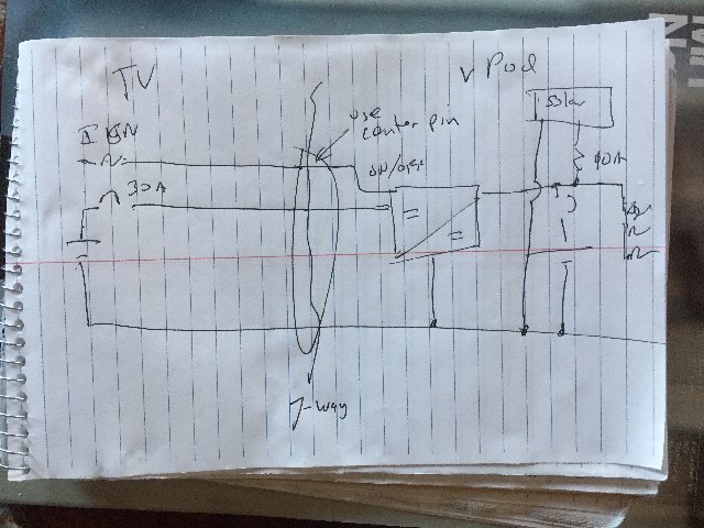 |
||||
|
1994 Chinook Concourse
1995 RV6A Experimental Aircraft 2015 Rpod 179 - sold |
||||
 |
||||
|
StephenH
podders Helping podders - pHp

Joined: 29 Nov 2015 Location: Wake Forest, NC Online Status: Offline Posts: 6289 |
Post Options
Quote Reply
Posted: 04 Apr 2020 at 9:11pm |
|||
|
||||
|
StephenH
Happy is the man that findeth wisdom,... ouR escaPOD mods Former RPod 179 Current Cherokee Grey Wolf 24 JS |
||||
|
||||
|
offgrid
Senior Member
Joined: 23 Jul 2018 Online Status: Offline Posts: 5290 |
Post Options
Quote Reply
Posted: 04 Apr 2020 at 6:49pm |
|||
Can’t tell exactly what you mean by the tap coming from the block but you need to find a line that’s hot when the ignition is on and feed that to the relay coil, right? The relay contacts need to be fed from the start battery via your new high current circuit breaker. The old 12v feed via the 7 way needs to be disconnected somewhere now that you will be using the dc/dc converter, doesn’t matter if it’s on the TV or trailer side, but if on the trailer side the breakaway needs to still be connected to your trailer battery. I don’t know where that connection is made so I thought I’d mention it. A test to be sure it still works after you’re done with your rewiring might be the best way. |
||||
|
1994 Chinook Concourse
1995 RV6A Experimental Aircraft 2015 Rpod 179 - sold |
||||
|
||||
|
StephenH
podders Helping podders - pHp
Joined: 29 Nov 2015 Location: Wake Forest, NC Online Status: Offline Posts: 6289 |
Post Options
Quote Reply
Posted: 04 Apr 2020 at 6:16pm |
|||
|
The tap goes into the fuse block to take the place of an existing fuse which gets inserted into the tap. Then there is a separate fused line that comes off that that will go to the relay. I need to figure out exactly which fuse in the block will get the tap. No, I had not planned on disconnecting it. I may see what fuse controls it and if I can do so without affecting anything else, remove the fuse to disable that circuit. I had originally thought just to leave it but you are right. With the dedicated charge circuit, it would not be needed. As for the breakaway switch, it would have to get power from the battery since otherwise, it would not work if the trailer broke away. That is another reason I did not do much with the wiring that was at the A frame other than to connect in the powerpole connector for the solar suitcase. and to insulate the connections so there wouldn't be a short.
|
||||
|
StephenH
Happy is the man that findeth wisdom,... ouR escaPOD mods Former RPod 179 Current Cherokee Grey Wolf 24 JS |
||||
|
||||
|
offgrid
Senior Member
Joined: 23 Jul 2018 Online Status: Offline Posts: 5290 |
Post Options
Quote Reply
Posted: 04 Apr 2020 at 5:02pm |
|||
|
Ok, here's the paragragh that confused me:
"Yes, that is exactly what I am planning. I have purchased a fuse block tap which inserts in place of the regular fuse and has two slots. One takes the original fuse for the circuit and the other is the fuse for the tap circuit. That will connect to the relay coil." I didn't put that in the schematic bc I didn't know where it went. Is that coming off the existing ignition circuit? Also, are you disconnecting the old 12V feed from the 7 way? You shouldn't want or need that anymore. Finally, not sure how it is wired but take a look at the breakaway switch for the trailer brakes to be sure it still gets power from the trailer battery when the cable is pulled.
|
||||
|
1994 Chinook Concourse
1995 RV6A Experimental Aircraft 2015 Rpod 179 - sold |
||||
|
||||
|
StephenH
podders Helping podders - pHp
Joined: 29 Nov 2015 Location: Wake Forest, NC Online Status: Offline Posts: 6289 |
Post Options
Quote Reply
Posted: 04 Apr 2020 at 1:50pm |
|||
|
I'm having a bit of trouble getting a picture to show. Essentially, your sketch is what I am planning. There may be some minor differences between what your sketch shows and what I have in mind. |
||||
|
StephenH
Happy is the man that findeth wisdom,... ouR escaPOD mods Former RPod 179 Current Cherokee Grey Wolf 24 JS |
||||
|
||||
|
offgrid
Senior Member
Joined: 23 Jul 2018 Online Status: Offline Posts: 5290 |
Post Options
Quote Reply
Posted: 04 Apr 2020 at 11:25am |
|||
|
Re the wire gauge for the negative conductor, as with the positive it needs to have an ampacity higher than the rating of the cb that you're using for that circuit. So if that's say a 60A breaker it would need to be 6AWG even it its short. You could remove the locknut from the gland and thread it onto a female npt to conduit slip fitting, something like this: Then glue the slip fitting to your conduit and glue the assemby into a hole drilled in the trailer floor. On the wiring, I'm a bit lost again without a schematic. Here's roughly what I think you're planning, can you confirm, modify, or add as needed?  |
||||
|
1994 Chinook Concourse
1995 RV6A Experimental Aircraft 2015 Rpod 179 - sold |
||||
|
||||
|
StephenH
podders Helping podders - pHp
Joined: 29 Nov 2015 Location: Wake Forest, NC Online Status: Offline Posts: 6289 |
Post Options
Quote Reply
Posted: 04 Apr 2020 at 10:28am |
|||
|
||||
|
StephenH
Happy is the man that findeth wisdom,... ouR escaPOD mods Former RPod 179 Current Cherokee Grey Wolf 24 JS |
||||
|
||||
|
offgrid
Senior Member
Joined: 23 Jul 2018 Online Status: Offline Posts: 5290 |
Post Options
Quote Reply
Posted: 04 Apr 2020 at 6:45am |
|||
|
What you have in mind should work. It gets a bit hard to understand circuit design without a schematic so you might have already done this but if not you should install a fuse or circuit breaker at the TV battery before the new relay if you haven't already. That can be rated at 40 or 50A with the devices and wire gauge you have on your list. I assume you will drive the relay coil from a wire tapped to your ignition switch? You'll still need the battery cb or fuse for the trailer battery as well, since both are current sources both need to be protected.
Now that you have run a separate trailer connector for 12V power from your TV the other way you could do this would be to run the wire tapped from your ignition to the 12V pin on your 7 way connector which is no longer being used, and then from the trailer side of the 7 way to the on/off switch on your dc/dc converter. That would save you needing to install the isolation relay.
As far as using the trailer chassis ground that should be fine but do use the same gauge wire to connect to the chassis that you are using coming from your battery, otherwise that piece of wire will become your weak link. Regardless of what FR did when they made the trailer I'd be tempted to avoid using spray foam insulation, it holds water whch will splash up against the bottom of the trailer. I would use a waterproof caulk instead. The "proper" way to do it would probably be to use a cable gland fitting mounted to a short piece of pvc conduit which goes up through the floor. |
||||
|
1994 Chinook Concourse
1995 RV6A Experimental Aircraft 2015 Rpod 179 - sold |
||||
|
||||
|
StephenH
podders Helping podders - pHp
Joined: 29 Nov 2015 Location: Wake Forest, NC Online Status: Offline Posts: 6289 |
Post Options
Quote Reply
Posted: 03 Apr 2020 at 9:44pm |
|||
|
The replacement arrived and is installed. I ordered this one: As for recent mods, I installed a Renogy DC-DC On-Board Battery Charger. The model is DCC1212-20. It is a 20A charger, which should be sufficient to charge the battery while towing without putting too much strain on the TV's alternator. Unfortunately, I found that one can't simply tap into the RPod's electric supply to run it. It ends up using the battery instead of the TV's power. Since there is no such thing as a free lunch or perpetual motion, it just would not work so it is installed but currently not connected. I'll post pictures once everything is done. I purchased the charger direct from Renogy. I took advantage of the recent sale and saved some money on the purchase. What I am working on is a dedicated power circuit. I had previously purchased some AWG6 THHN cable which I ended up not using. Today I ran it from the engine compartment of the Frontier to the back bumper. After I uninstalled the other one, I noticed that it was working
differently, like something inside shook loose. The lever is moving
farther and it now has a definitive snap when tripping or resetting were
before it seemed a little mushy. However, the new one is in and I am
not going to install the old one in that circuit again. It may get
repurposed for this project, but I am not fully decided on that. The parts I am waiting on are a 2-pole socket with the bumper mounting plate and a waterproofing boot for the Frontier. For the RPod, I ordered a 2-pole plug. These were ordered from eTrailer. To make it work, I ordered a Battery Isolator Relay. This will sit under the hood of the Frontier and it will only provide power while the engine is running. I opted for this type over the voltage sensitive type because I read that those don't work well for LiFePO4 batteries because the Li battery's voltage prevents the start battery voltage from dropping to the point where the charger cuts off. Since this works with a relay and is merely "clever" instead of "smart" it should work better as once the engine is shut off, the relay should open and power to the RPod should be disconnected. "Smart" devices are not always suitable. This is one of those cases. Since the maximum draw of the DC to DC charger would be about 30A, this should be more than sufficient. Once these arrive, I will get them installed. The Frontier will be relatively easy. For the RPod, I have to figure out how to run conductors from the compartment where the battery and charger are installed. Inside the compartment I modified and where the battery sits, some of the floor is cut away for the water lines to cross from the water heater side to get to the bath. I am thinking of drilling a hole there just big enough for the wires and then once I run them, sealing the opening with some expanding foam since it looks like that is what the factory did for items penetrating the bottom of the RPod. Would this be an acceptable way to do this? I am thinking that I only need to run one conductor though the hole for the power side. The negative can be connected through the existing connections inside the RPod and then a shorter wire can be used to connect the negative side of the connector through to the TV where a short cable will be used to tie the negative side to the truck frame. According to the chart in the Renogy manual, I should use an 8 AWG wire for up to 16 ft. If it is only 8 ft. needed, then 10 AWG would be acceptable. I'm not sure how much would be needed, so I'll probably just go with AWG6 to be safe. Well, that about catched up to current status.
|
||||
|
StephenH
Happy is the man that findeth wisdom,... ouR escaPOD mods Former RPod 179 Current Cherokee Grey Wolf 24 JS |
||||
|
||||
|
Post Reply
|
Page <1 1516171819 58> |
| Forum Jump | Forum Permissions You cannot post new topics in this forum You cannot reply to topics in this forum You cannot delete your posts in this forum You cannot edit your posts in this forum You cannot create polls in this forum You cannot vote in polls in this forum |


